router ospf 1 PID :1 PROCESS ID
router id 0.0.0.1 RID ROUTER ID = ISMI
hangi interfacelerde aktif olacak
0.0.0.0 255.255.255.255 area 0
DOWN: Hello almadım
INIT: Hello aldım. Gönderenin Router id si var
TWO WAY: Hello alıyorum. İçinde benim router id bilgim var.
EXSTRAT: Mtu bilgin nedir ? RID ile master seçimi
EXCHANGE : Kimde ne var
LOADING : Bilgilerin takası
Komsuluk Kurmak için:
1- Aynı subnette olacaklar
2- Mtu Aynı olacak
3-Aynı Area olacak
4- RID router id farklı olacak
5- Hello dead timer aynı olacak
6-Authentication key varsa aynı olacak
When Open Shortest Path First (OSPF) is enabled on a router or when a router configured for OSPF is powered up, it tries to discover its OSPF neighbors and synchronize its database with them. Routers are said to be OSPF neighbors when they see their router ID in the received hello packet and the status of their OSPF relationship transitions toTwo-way.
OSPF neighbors then exchange routing information with each other. Once their databases are updated and synchronized, the status of their OSPF relationship changes to Full. However, the status of the OSPF relationship between OSPF neighbors does not always transition to Full and might remain stuck in Two-wayinstead.
Resolution
This is expected behavior on routers running OSPF. OSPF routers on multi-access segments synchronize their databases with their Designated Router (DR) or a Backup Designated Router (BDR) only. The OSPF status between two routers transitions to Full only if at least one of them is a DR or a BDR. The state remains Two-way between a pair of routers if both are drothers.
For more information on the relationship between OSPF routers stuck in the two-way state, refer to Why Does the show ip ospf neighbor Command Reveal Neighbors Stuck in Two-Way State?
Troubleshooting Commands:
1) show ip ospf neighbors....This command will show you states of your neighbor and dead timer.
Example:
Router#sh ip os ne
Neighbor ID Pri State Dead Time Address Interface
1.1.1.1 1 FULL/DR 00:00:38 10.1.1.1 FastEthernet0/0
1.1.1.1 1 FULL/DR 00:00:38 10.1.1.1 FastEthernet0/0
1) Show ip ospf int brief ...This command will give you OSPF property briefly on each interface.
Example:
Router#sh ip os int bri
Interface PID Area IP Address/Mask Cost State Nbrs F/C
Fa0/0 100 0 10.1.1.2/24 10 BDR 1/1
Interface PID Area IP Address/Mask Cost State Nbrs F/C
Fa0/0 100 0 10.1.1.2/24 10 BDR 1/1
3) Show ip ospf int <inteface no>...This command will give detail OSPF interface information like network-type,authentication type and key, interface mask,cost etc.
Example:
Router#sh ip os int fa0/0
FastEthernet0/0 is up, line protocol is up
Internet Address 10.1.1.2/24, Area 0
Process ID 100, Router ID 10.1.1.2, Network Type BROADCAST, Cost: 10
Enabled by interface config, including secondary ip addresses
Transmit Delay is 1 sec, State BDR, Priority 1
Designated Router (ID) 1.1.1.1,Interface address 10.1.1.1
Backup Designated router (ID) 10.1.1.2, Interface address 10.1.1.2
Timer intervals configured, Hello 10, Dead 40, Wait 40, Retransmit 5
oob-resync timeout 40
Hello due in 00:00:06
Supports Link-local Signaling (LLS)
Cisco NSF helper support enabled
IETF NSF helper support enabled
Index 1/1, flood queue length 0
Next 0x0(0)/0x0(0)
Last flood scan length is 1, maximum is 1
Last flood scan time is 0 msec, maximum is 0 msec
Neighbor Count is 1, Adjacent neighbor count is 1
Adjacent with neighbor 1.1.1.1 (Designated Router)
Suppress hello for 0 neighbor(s)
4) Sh int (interface-no>....This command will give you physical link parameter like link state,MTU(Which is imp factor in ospf while exchanging database and need to same on both site>.
Example:
Router#sh int fa0/0 | in MTU | up
FastEthernet0/0 is up, line protocol is up
MTU 1500 bytes, BW 10000 Kbit/sec, DLY 1000 usec,
FastEthernet0/0 is up, line protocol is up
MTU 1500 bytes, BW 10000 Kbit/sec, DLY 1000 usec,
For MTU ,you need to check on (Routing) IP MTU that's will gonna stuck your OSPF process in ex-start state if both side device don't have same MTU , default both MTUs are same on IOS platform but you can change using "ip mtu" command under interface on the router and on Switch ,you can set system routing MTU.
Example:
Router#sh ip int fa0/0 | in MTU
MTU is 1400 bytes
mtu sizeları farklı ise bile görmezden gel.Router1(config-if)#interface fa 0/0
interface Ethernet0/0MTU is 1400 bytes
mtu sizeları farklı ise bile görmezden gel.Router1(config-if)#interface fa 0/0
Router1(config-if)# ip ospf mtu-ignore
ip address 172.17.1.1 255.255.255.0
ip mtu 1400
ip ospf mtu-ignore
RID = SHOW IP OSPF
- Show ip ospf neighbors.
- show ip ospf rib
- Show ip ospf interface
- Show ip protocols
- Debug ip ospf adj
- Debug ip ospf hello
- Show ip ospf database (lsa paketleri)
Cost: 100 Mbps(Megabit) / interface bandwidth(uses best way choice)
bandwith hesabındaki 100 megabiti 2000 megabit yapmak icin
router ospf 1
auto-cost reference-bandwith 2000(megabit)
Lesson learned: Don’t block OSPF multicast addresses 224.0.0.5 and 224.0.0.6.
- Show ip ospf neighbors.
- Show ip ospf interface
- Show ip protocols
- Debug ip ospf adj
- Debug ip ospf hello
The OSPF protocol is a link-state routing protocol, which means that the routers exchange topology information with their nearest neighbors. The topology information is flooded throughout the AS.
shortest path first or SPF algorithm and the same thing apply to OSPF.
Cisco's recommendation is each area has a maximum 50 routers per OSPF area and no more than two area or areas per ABR in addition to area 0.
Ospf protocol number is 89
Cost: 100 Mbps(Megabit) / interface bandwidth(uses best way choice)
we seperate the network topology to different area because of LSDB will grow, so I've separated your network from AREA.
Dikkat edilecek husus her area nın bir lsdb database'i vardır ve cost hesablaması yaparken yanlızca buluğundu area için bu hesabı yapar.
LSA1 and LSA2 messages will only shared within the respective or same Area. dont pass from ABR.
Other LSA Packages (LSA 3-4-5-7) will come to us over ABR or ASBR router.
ospf'in altın backbonedaki routeları bu komutla anons edebilirsin.
router ospf 1
default-information originate always
Ospf routing manipulation
R2(config)#interface fastEthernet 1/0
R2(config-if)#ip ospf cost 50
Dr selection ;
- Manual configuration of the router ID.
- Highest IP address on a loopback interface.
- Highest IP address on a non-loopback interface.
R1(config)#router ospf 1
R1(config-router)#router-id 111.111.111.111
veya R1(config)#interface fastEthernet 0/0
R1(config-if)#ip ospf priority 200 (default 1 değeridir, 0 asla dr olamazsın)R2#show ip ospf neighbor Neighbor ID Pri State Dead Time Address Interface
192.168.12.1 1 FULL/DR 00:00:37 192.168.12.1 FastEthernet0/0 Defaultta hello 10 dead 40 saniyedir. Bu süre azaltılabilir.
ip ospf hello-interval
|
| 40 sec / 120 sec |
R1#show ip ospf interface FastEthernet 0/0 | include intervals
Timer intervals configured, Hello 10, Dead 40, Wait 40, Retransmit 5 (config)#interface FastEthernet 0/0
(config-if)#ip ospf hello-interval 1
(config-if)#ip ospf dead-interval 3
R1(config-if)#ip ospf dead-interval 1
R1(config-if)#ip ospf dead-interval minimal hello-multiplier 3
R1#show ip ospf interface FastEthernet 0/0 | include intervals Timer intervals configured, Hello 333 msec, Dead 1, Wait 1, Retransmit 5PASSİVE İNTERFACE
R1(config)#router ospf 1
R1(config-router)#passive-interface FastEthernet 0/1

R1(config)#router ospf 1
R1(config-router)#passive-interface default
R1(config-router)#no passive-interface FastEthernet 0/0
Network advertise Ospf ; baska bir cihaz tarafından anos edilen 192.168.45.0 ipsine R3 ün erişmemesi icin. R3# (config)#ip access-list standard FA
(config-std-nacl)#deny 192.168.45.0 0.0.0.255
(config-std-nacl)#permit any
(config)#router ospf 1
(config-router)#distribute-list FA in
R3#show ip route 192.168.45.0
% Network not in table
EIGRP’de olabilecek en büyük hop count değeri 224’tür.
Router(config)#access-list 50 deny 10.0.0.0 0.0.0.255
Router(config)#access-list 50 permit any
Router(config)#router eigrp 1
Router(config-router)#distribute-list 50 out
Router(config)#access-list 50 permit any
Router(config)#router eigrp 1
Router(config-router)#distribute-list 50 out
R4(config)#ip prefix-list INTO-AREA3 deny 2.2.2.2/32
R4(config)#ip prefix-list INTO-AREA3 permit 0.0.0.0/0 le 32
This prefix-list will deny 2.2.2.2 /32 and allow all other prefixes. Now we have to apply it to the area:
R4(config)#router ospf 1
R4(config-router)#area 3 filter-list prefix INTO-AREA3 in
Yukarıdaki yapılandırma eigrp’nin 10.0.0.0/24 network’ünü hiç bir interface’inden öğretmemesini sağlar. ACL’nin sonundaki permit any satırı gereklidir aksi takdirde sondaki implicit deny yüzünden hiç bir rota öğretilmez
Alta ise öğretme olayını göstermektedir.
ip prefix-list EFT_REDIS seq 5 permit 10.205.28.5/32
ip prefix-list EFT_REDIS seq 10 permit 10.205.28.7/32
route-map RM_EFT_REDIS permit 10
match ip address prefix-list EFT_REDIS
router eigrp 2
redistribute static route-map RM_EFT_REDIS
Alta ise öğretme olayını göstermektedir.
ip prefix-list EFT_REDIS seq 5 permit 10.205.28.5/32
ip prefix-list EFT_REDIS seq 10 permit 10.205.28.7/32
route-map RM_EFT_REDIS permit 10
match ip address prefix-list EFT_REDIS
router eigrp 2
redistribute static route-map RM_EFT_REDIS
RIP metric olarak hop sayısını kullanan bir distance vector protokolüdür. 2 versiyon olarak geliştirilmiştir. UDP 520 numaralı portu kullanır ve administrative distance ı 120’dir. Maksimum hop sayısı 15’tir. RIP kullanan router’lar tüm topolojiyi bilmezler. RIP kullanan routerlar 30 saniyede bir komşularına update bilgisi yollarlar. Routing update’lerinde, routing tablosu yalnızca komşu router’lara gönderilir ve bir seferde en fazla 25 route gönderilebilir. Eğer 25’ten fazlaysa iki parça olarak update yollanır. Convergence süresi uzundur. Bundan dolayı büyük ölçekli networklerde kullanışsızdır.
- LSA Type 1: Router LSA
- LSA Type 2: Network LSA
- LSA Type 3: Summary LSA
- LSA Type 4: Summary ASBR LSA
- LSA Type 5: Autonomous system external LSA
- LSA Type 6: Multicast OSPF LSA
- LSA Type 7: Not-so-stubby area LSA
- LSA Type 8: External attribute LSA for BGP
LSA 1(ROUTER LINK STATES)
Providing information about the devices around them.
Her router”ın kendi area”sı içindeki routerlar için oluşturduğu LSA”lerdir. Böylece her router kendine doğrudan bağlı linkler ile ilgili diğer routerları bilgilendirebilir. Bu tip LSA”ler sadece aynı area içinde dağıtılırlar.
(Router) in the same way around the LSA information gives.
Your name, your neighbor, your distance to them.
For drawing the topology of devices on the same AREA.
LSA 2 ( NETWORK LINK STATES)
Network LSA”leri DR”lar (Designated Router) tarafından dağıtılırlar. Network LSA”leri, aynı network segmentine bağlı routerları listeler ve diğer routerlara bildirir. Böylece her router aynı network segemntindeki diğer routerlardan haberdar olur. Network LSA”leri de aynı area içinde dağıtılırlar. Farklı bir area”ya dağıtılmaları mümkün değildir.
all these devices choose a DR router among themselves.
Only DR sends network information to other routers.
They choose who is the King.
LSA 3 ( SUMMARY NET LINK STATES)
ABR : It distributes the LSA 3 packages that you create yourself, not LSA 1 or LSA 2 packages.
ABR Summary LSA”leri ABR routerlar tarafından dağıtılırlar. Bir area içindeki networkler diğer arae”lara ABR Summary LSA”ler tarafından duyurulur. Summary işlemi varsayılan olarak routerlarda açık değildir. ABR routerların bu summary işlemini gerçekleştirmesi için aşağıdaki komut ABR routerda çalıştırılmalıdır
Produced by ABR. It is used to transfer information from one Area to another Area. For example, the incoming LSA1 information is converted by LSA 3.
The NETWORK information in the side area sent to us by ABR nin LSA 3 package.
It shows as "O IA" in the Routing Table.
LSA 4 ( SUMMARY ASB LINK STATES)
It is called Router ASBR (Autonomous System Border Router) which works with different routing protocols.
They are created and distributed by ABRs. And there is only information in it. Who is ASBR
It shows as "O IA" in the Routing Table
LSA 5 ( EXTERNAL LINKS STATES)
ASBR gives information about (Rip, Eigrp) networks is in LSA 5.
Inside (Rip, Eigrp) are learned NETWORK information.
It shows as "O E1/E2" in the Routing Table.
LSA 7 ( External Link States)
ASBR creates both LSA 5 and LSA 7 . They are same package like LSA type 5.
LSA 6
There are for multicast ospf applications.
LSA 8
Related to Bgp.
LSA 9,10,11
Related to MPLS
Link id :
If there is under ;
LSA 1 = the Router ID of the Neighbour
LSA 2 = IP address of DR
LSA 3 = Subnet number
Link Count :
LSA 1 type is only written below.
It gives the number of direct links.
P2P counts "two", others are "one".
O: Shows network information from the same Area.
O IA: Network information from different areas.
E1: Shows OSPF external network information sent by ASBR. The metric expression is calculating whenever a Router passes.
E2: Shows OSPF external network information sent by ASBR. The metric expression is not calculating . The default statement
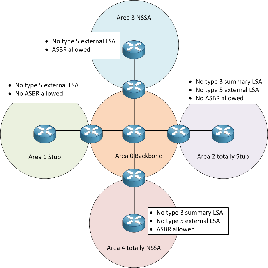
AREA 0 at the same time that means BACKBONE.
We have five different areas.
STANDARD AREA or TRANSIT AREA
STUB AREA
TOTALLY STUB AREA
NSSA
NSSA TOTALLY STUBBY AREA
STANDART AREA
LSA 1-2-3-4-5 packages are allowed. Only LSA 7 packages can not accept.
LSA 1-2 : It is shown as "O" in the routing table.
LSA 3-4 :The ABR sends the LSA 3-4-5 (also we called "IA")
LSA5 : ASBR sends the LSA 5.(it is shown as "E1orE2" different protocol)
STUB AREA
Only LSA 1-2-3 packages are accepted.
So LSA can not accept 4-5-7 packages.
LSA 4-5 packages never sent from ABR. LSA 7 never sent from ASBR.
We will be able to see the networks of other AREA s that come with ABR's own LSA 3 package. We will see them as "O IA" (These networks belong to other AREA s.)
It will only send its own LSA 3 packages also DEFAULT ROUTE.
conf t
router ospf 10
area 1 stub
TOTALLY STUBBY AREA
It is a feature of Cisco.
We want to access all other information with a DEFAULT ROUTE except for LSA 1 and LSA 2 .
ABR will give us a default route :) instead of O E1 / E2 and O IA we just have one default route.
ABR#
conf t
router ospf 10
area 5 stub NO SUMMARY (We will do a small change at ABR)
We dont get any messages from Lsa type 3,4,5 , we just get default route instead of Lsa messages.
NSSA
LSA 1-2-3-7 packages are accepted.
NSSA areas always need an ASBR router.
Because STUB accepted LSA 1-2-3. There is an extra LSA 7.
conf t router
ospf 13
area 10 nssa
NSSA TOTALLY STUBBY AREA
It is a feature of Cisco.
LSA 1-2 & LSA 7 will also be DEFAULT ROUTE(O*N2) (we exclued Lsa 3)
conf t
router ospf 13
area 10 nssa no-summary
VIRTUAL LINKS
show ip ospf
show ip ospf interface
show ip protocol
All of these commands show us ROUTER-ID.
Normally the LSAs will be refreshed every 30 minutes.
This rule does not apply to LSAs learned on Virtual Link.(DoNotAge)
SHOW IP OSPF VIRTUAL-LINK
Default-information Orginate : Tüm ospf cihazlar ıcın default rota orası olacaktır.
router ospf 65101
network 172.16.101.1 0.0.0.0 area 0
default-information originate

R1;
router ospf 13
network 1.1.1.1 0.0.0.0 area 0
R2;
router ospf 13
area 1 virtual-link 3.3.3.3 (There is R3 router id)
network 1.1.1.2 0.0.0.0 area 0
network 2.2.2.2 0.0.0.0 area 1
R3;
router ospf 13
area 1 virtual-link 2.2.2.2 (There is R2 router id)
network 2.2.2.3 0.0.0.0 area 1
network 3.3.3.3 0.0.0.0 area 2
R4;
router ospf 13
network 3.3.3.4 0.0.0.0 area 2
OSPF KEY SECURİTY
hostname R1
!
interface FastEthernet0/0
 ip address 192.168.12.1 255.255.255.0
 ip ospf message-digest-key 1 md5 MYPASS
 ip ospf authentication message-digest
!
router ospf 1
 network 192.168.12.0 0.0.0.255 area 0
 area 0 authentication message-digest
!
end
hostname R2
!
interface FastEthernet0/0
ip address 192.168.12.2 255.255.255.0
ip ospf message-digest-key 1 md5 MYPASS
ip ospf authentication message-digest
!
router ospf 1
network 192.168.12.0 0.0.0.255 area 0
area 0 authentication message-digest
!
end
set protocols ospf export redis-static (static route redistribution)
set policy-options policy-statement redis-static term static from protocol static
set protocols ospf area 0.0.0.0 interface reth6.0 metric 11
set protocols ospf area 0.0.0.0 interface reth6.0 priority 255
set routing-options router-id 222.222.222.222
set policy-options policy-statement redis-static term static from route-filter 1.1.0.0/16 exact
set policy-options policy-statement redis-static term static then accept
Huawei

Bu bölümde tek bir alan için OSPF konfigurasyonu yapacağız, Router-Id belirlemeyi, hello ve dead sürelerini belirlemeyi, default-route’u OSPF de anons etmeyi ve DR ve BDR seçimini yaptırmayı göreceğiz.
1. OSPF routing protokolü için ortam hazırlayalım
Lab konfigürasyonu için temel sistem ve ip address yapılandırmasını kuralım.
<Huawei>system-viewEnter system view, return user view with Ctrl+Z.[Huawei]sysname CLIGURU-R1[CLIGURU-R1]interface GigabitEthernet 0/0/1[CLIGURU-R1-GigabitEthernet0/0/1]ip address 10.0.12.1 24[CLIGURU-R1-GigabitEthernet0/0/1]quit[CLIGURU-R1]interface GigabitEthernet 0/0/0[CLIGURU-R1-GigabitEthernet0/0/0]ip address 10.0.13.1 24[CLIGURU-R1-GigabitEthernet0/0/0]quit[CLIGURU-R1]interface LoopBack 0[CLIGURU-R1-LoopBack0]ip address 10.0.1.1 24 |
<Huawei>system-viewEnter system view, return user view with Ctrl+Z.[Huawei]sysname CLIGURU-R2[CLIGURU-R2]interface GigabitEthernet 0/0/1[CLIGURU-R2-GigabitEthernet0/0/1]ip address 10.0.12.2 24[CLIGURU-R2-GigabitEthernet0/0/1]quit[CLIGURU-R2]interface LoopBack 0[CLIGURU-R2-LoopBack0]ip address 10.0.2.2 24 |
<Huawei>system-viewEnter system view, return user view with Ctrl+Z.[Huawei]sysname CLIGURU-R3[CLIGURU-R3]interface GigabitEthernet 0/0/0[CLIGURU-R3-GigabitEthernet0/0/0]ip address 10.0.13.3 24[CLIGURU-R3-GigabitEthernet0/0/0]quit[CLIGURU-R3]interface LoopBack 0[CLIGURU-R3-LoopBack0]ip address 10.0.3.3 24[CLIGURU-R3-LoopBack0]quit[CLIGURU-R3]interface LoopBack 2[CLIGURU-R3-LoopBack2]ip address 172.16.0.1 24 |
2. OSPF konfigürasyonu oluşturalım.
Router ID yi 10.0.1.1 (Manuel olarak da loopback olmadan router-id girilebilir. Kolaylık için loopback’ipsi ile aynı girdik)olarak verelim. OSPF process 1 (default process)’i kullanalım, network ağlarınıda spesific olarak 10.0.1.0/24, 10.0.13.0/24 ve 10.0.12.0/24 networklerinde area0 ’ın bir parçası olarak belirtelim.
[CLIGURU-R1]ospf 1 router-id 10.0.1.1[CLIGURU-R1-ospf-1]area 0[CLIGURU-R1-ospf-1-area-0.0.0.0]network 10.0.1.0 0.0.0.255[CLIGURU-R1-ospf-1-area-0.0.0.0]network 10.0.13.0 0.0.0.255[CLIGURU-R1-ospf-1-area-0.0.0.0]network 10.0.12.0 0.0.0.255 |
Farklı process ID’leri farklı link-state veritabanları oluşturur, bundan dolayı bütün routerların aynı OSPF process ID’sine sahip olmasına dikkat edin. Wildcard mask’i network komutunda spesifik olarak o network için girilmelidir.
CLIGURU-R2’de manuel olarak 10.0.2.2 ‘yi router-id olarak konfigure edelim. OSPF process-id’miz 1 ve anons ettiğimiz network segmentleri 10.0.12.0/24 ve 10.0.2.0/24 olarak Area0 içinde yer alsın.
[CLIGURU-R2 ]id 10.0.2.2[CLIGURU-R2]area 0[CLIGURU-R2-ospf-1-area-0.0.0.0]network 10.0.2.0 0.0.0.255[CLIGURU-R2-ospf-1-area-0.0.0.0]network 10.0.12.0 0.0.0.255 |
Manuel olarak 10.0.3.3 ‘yi router-id olarak konfigure edelim. OSPF process-id’miz 1 ve anons ettiğimiz network segmentleri 10.0.3.0/24 ve 10.0.13.0/24 olarak Area0 içinde yer alsın.
[R3id 10.0.3.3[CLIGURU-R3-ospf-1]area 0[CLIGURU-R3-ospf-1-area-0.0.0.0]network 10.0.3.0 0.0.0.255[CLIGURU-R3-ospf-1-area-0.0.0.0]network 10.0.13.0 0.0.0.255 |
3. OSPF konfigürasyonunu kontrol edelim.
OSPF route eşleşmesi tamamlandıktan sonra , CLIGURU-R1 ,CLIGURU-R2 ve CLIGURU-R3’ün routing tablosuna bakalım.
<CLIGURU-R1>display ip routing-tableRoute Flags: R – relay, D – download to fib—————————————————————————Routing Tables: PublicDestinations : 10 Routes : 10Destination/Mask Proto Pre Cost Flags NextHop Interface10.0.1.0/24 Direct 0 0 D 10.0.1.1 LoopBack010.0.1.1/32 Direct 0 0 D 127.0.0.1 LoopBack010.0.2.2/32 OSPF 10 1 D 10.0.12.2 GigabitEthernet0/0/110.0.3.3/32 OSPF 10 1 D 10.0.13.3 GigabitEthernet0/0/010.0.12.0/24 Direct 0 0 D 10.0.12.1 GigabitEthernet0/0/110.0.12.1/32 Direct 0 0 D 127.0.0.1 GigabitEthernet0/0/110.0.13.0/24 Direct 0 0 D 10.0.13.1 GigabitEthernet0/0/010.0.13.1/32 Direct 0 0 D 127.0.0.1 GigabitEthernet0/0/0127.0.0.0/8 Direct 0 0 D 127.0.0.1 InLoopBack0127.0.0.1/32 Direct 0 0 D 127.0.0.1 InLoopBack0 |
<CLIGURU-R2>display ip routing-tableRoute Flags: R – relay, D – download to fib——————————————————————————Routing Tables: PublicDestinations : 9 Routes : 9Destination/Mask Proto Pre Cost Flags NextHop Interface10.0.1.1/32 OSPF 10 1 D 10.0.12.1 GigabitEthernet0/0/110.0.2.0/24 Direct 0 0 D 10.0.2.2 LoopBack010.0.2.2/32 Direct 0 0 D 127.0.0.1 LoopBack010.0.3.3/32 OSPF 10 2 D 10.0.12.1 GigabitEthernet0/0/110.0.12.0/24 Direct 0 0 D 10.0.12.2 GigabitEthernet0/0/110.0.12.2/32 Direct 0 0 D 127.0.0.1 GigabitEthernet0/0/110.0.13.0/24 OSPF 10 2 D 10.0.12.1 GigabitEthernet0/0/1127.0.0.0/8 Direct 0 0 D 127.0.0.1 InLoopBack0127.0.0.1/32 Direct 0 0 D 127.0.0.1 InLoopBack0 |
<CLIGURU-R3>display ip routing-tableRoute Flags: R – relay, D – download to fib——————————————————————————Routing Tables: PublicDestinations : 11 Routes : 11Destination/Mask Proto Pre Cost Flags NextHop Interface10.0.1.1/32 OSPF 10 1 D 10.0.13.1 GigabitEthernet0/0/10.0.2.2/32 OSPF 10 2 D 10.0.13.1 GigabitEthernet0/0/010.0.3.0/24 Direct 0 0 D 10.0.3.3 LoopBack010.0.3.3/32 Direct 0 0 D 127.0.0.1 LoopBack010.0.12.0/24 OSPF 10 2 D 10.0.13.1 GigabitEthernet0/0/010.0.13.0/24 Direct 0 0 D 10.0.13.3 GigabitEthernet0/0/010.0.13.3/32 Direct 0 0 D 127.0.0.1 GigabitEthernet0/0/027.0.0.0/8 Direct 0 0 D 127.0.0.1 InLoopBack0127.0.0.1/32 Direct 0 0 D 127.0.0.1 InLoopBack0172.16.0.0/24 Direct 0 0 D 172.16.0.1 LoopBack2172.16.0.1/32 Direct 0 0 D 127.0.0.1 LoopBack2 |
CLIGURU-R1 ve CLIGURU-R2 arasında 10.0.1.1’e, de CLIGURU-R2 ve CLIGURU-R3 arasında 10.0.3.3’e pingatarak networkü kontrol edelin.
<CLIGURU-R2>ping 10.0.1.1PING 10.0.1.1: 56 data bytes, press CTRL_C to breakReply from 10.0.1.1: bytes=56 Sequence=1 ttl=255 time=30 msReply from 10.0.1.1: bytes=56 Sequence=2 ttl=255 time=60 msReply from 10.0.1.1: bytes=56 Sequence=3 ttl=255 time=40 msReply from 10.0.1.1: bytes=56 Sequence=4 ttl=255 time=30 msReply from 10.0.1.1: bytes=56 Sequence=5 ttl=255 time=30 ms— 10.0.1.1 ping statistics —5 packet(s) transmitted5 packet(s) received0.00% packet lossround-trip min/avg/max = 30/38/60 ms |
<CLIGURU-R2>ping 10.0.3.3PING 10.0.3.3: 56 data bytes, press CTRL_C to breakReply from 10.0.3.3: bytes=56 Sequence=1 ttl=254 time=60 msReply from 10.0.3.3: bytes=56 Sequence=2 ttl=254 time=80 msReply from 10.0.3.3: bytes=56 Sequence=3 ttl=254 time=30 msReply from 10.0.3.3: bytes=56 Sequence=4 ttl=254 time=80 msReply from 10.0.3.3: bytes=56 Sequence=5 ttl=254 time=80 ms— 10.0.3.3 ping statistics —5 packet(s) transmitted5 packet(s) received0.00% packet lossround-trip min/avg/max = 30/66/80 ms |
OSPF komşuluk durumuna display ospf peer komutuyla bakabiliriz.
<CLIGURU-R1>display ospf peerOSPF Process 1 with Router ID 10.0.1.1NeighborsArea 0.0.0.0 interface 10.0.12.1(GigabitEthernet0/0/1)’s neighborsRouter ID: 10.0.2.2 Address: 10.0.12.2State: Full Mode:Nbr is Master Priority: 1DR: 10.0.12.1 BDR: 10.0.12.2 MTU: 0Dead timer due in 35 secRetrans timer interval: 5Neighbor is up for 00:06:10Authentication Sequence: [ 0 ]NeighborsArea 0.0.0.0 interface 10.0.13.1(GigabitEthernet0/0/0)’s neighborsRouter ID: 10.0.3.3 Address: 10.0.13.3State: Full Mode:Nbr is Master Priority: 1DR: 10.0.13.1 BDR: 10.0.13.3 MTU: 0Dead timer due in 39 secRetrans timer interval: 5Neighbor is up for 00:03:58Authentication Sequence: [ 0 ] |
Display ospf peer komutuyla ospf komşuluklarını detaylı olarak inceleyebiliriz. Örnekteki ekran çıktısına bakarak CLIGURU-R1’in DR’ını 10.0.13.1 olarak belirlemiş. DR seçiminde sonsuz bir öncelik yoktur, yani DR durumu CLIGURU-R3’den CLIGURU-R1’e geçmeyecektir, geçmesi için OSPF process’i resetlenmelidir.
Display ospf peer brief komutu ile ospf komuşularının daha küçük bir çıktısını verir.
<CLIGURU-R1>display ospf peer briefOSPF Process 1 with Router ID 10.0.1.1Peer Statistic Information————————————————————————–Area Id Interface Neighbor id State0.0.0.0 GigabitEthernet0/0/1 10.0.2.2 Full0.0.0.0 GigabitEthernet0/0/0 10.0.3.3 Full————————————————————————– |
<R2>display ospf peer briefOSPF Process 1 with Router ID 10.0.2.2Peer Statistic Information————————————————————————–Area Id Interface Neighbor id State0.0.0.0 GigabitEthernet0/0/1 10.0.1.1 Full————————————————————————– |
<R3>display ospf peer briefOSPF Process 1 with Router ID 10.0.3.3Peer Statistic Information————————————————————————–Area Id Interface Neighbor id State0.0.0.0 GigabitEthernet0/0/0 10.0.1.1 Full————————————————————————– |
Ospf hello interval ve dead interval aralıklarını(sürelerini) değiştirelim.
Display ospf interface GigabitEthernet 0/0/0 komutu ile CLIGURU-R1 üzerinde default hello interval ve dead interval bilgilerini görüntüleyelim.
<CLIGURU-R1>display ospf interface GigabitEthernet 0/0/0OSPF Process 1 with Router ID 10.0.1.1InterfacesInterface: 10.0.13.1 (GigabitEthernet0/0/0)Cost: 1 State: DR Type: Broadcast MTU: 1500Priority: 1Designated Router: 10.0.13.1Backup Designated Router: 10.0.13.3Timers: Hello 10 , Dead 40 , Poll 120 , Retransmit 5 , Transmit Delay 1 |
Ospf’in hello ve dead interval’ini degiştirmek için ospf timer komutunu kullanırız.CLIGURU-R1 ‘in hello interval 15 ,dead interval 60 olarak değiştirelim.
[CLIGURU-R1]interface GigabitEthernet 0/0/0[CLIGURU-R1-GigabitEthernet0/0/0]ospf timer hello 15[CLIGURU-R1-GigabitEthernet0/0/0]ospf timer dead 60Oct 28 2014 15:56:17-08:00 CLIGURU-R1 %%01OSPF/3/NBR_DOWN_REASON(l)[1]:Neighbor state leaves full or changed to Down. (ProcessId=1, NeighborRouterId=10.0.3.3, NeighborAreaId=0,NeighborInterface=GigabitEthernet0/0/0,NeighborDownImmediate reason=Neighbor Down Due to Inactivity, NeighborDownPrimeReason=Interface Parameter Mismatch,NeighborChangeTime=2014-10-28 15:56:17-08:00) |
<CLIGURU-R1>display ospf interface GigabitEthernet 0/0/0OSPF Process 1 with Router ID 10.0.1.1InterfacesInterface: 10.0.13.1 (GigabitEthernet0/0/0)Cost: 1 State: DR Type: Broadcast MTU: 1500Priority: 1Designated Router: 10.0.13.1Backup Designated Router: 0.0.0.0Timers: Hello 15 , Dead 60 , Poll 120 , Retransmit 5 , Transmit Delay 1 |
CLIGURU-R1 üzerinde ospf komşuluk durumunu kontrol edelim.
<CLIGURU-R1>display ospf peer briefOSPF Process 1 with Router ID 10.0.1.1Peer Statistic Information————————————————————————–Area Id Interface Neighbor id State0.0.0.0 GigabitEthernet0/0/1 10.0.2.2 Full————————————————————————– |
Yukarıdaki ekran çıktısında , CLIGURU-R1’in sadece tek bir komşusunun, CLIGURU-R2 olduğunu göstermektedir.
OSPF hello interval ve dead interval değerleri CLIGURU-R1 ve CLIGURU-R3 üzerinde farklı, bundan dolayı CLIGURU-R1 ve CLIGURU-R3 OSPF komşuluğu kuramamaktadır.
Ospf timer komutu ile CLIGURU-R3 üzerinde GE0/0/0 içinde Hello 15, Dead 60 olarak değiştirelim.
[CLIGURU-R3]interface GigabitEthernet 0/0/0[CLIGURU-R3-GigabitEthernet0/0/0]ospf timer hello 15[CLIGURU-R3-GigabitEthernet0/0/0]ospf timer dead 60Oct 28 2014 16:02:55-08:00 CLIGURU-R3 %%01OSPF/4/NBR_CHANGE_E(l)[4]:Neighbor changes event:neighbor status changed. (ProcessId=1, NeighborAddress=10.0.13.1, NeighborEvent=LoadingDone, NeighborPreviousState=Loading, NeighborCurrentState=Full) |
<CLIGURU-R3>display ospf interface GigabitEthernet 0/0/0OSPF Process 1 with Router ID 10.0.3.3InterfacesInterface: 10.0.13.3 (GigabitEthernet0/0/0)Cost: 1 State: DR Type: Broadcast MTU: 1500Priority: 1Designated Router: 10.0.13.3Backup Designated Router: 10.0.13.1Timers: Hello 15 , Dead 60 , Poll 120 , Retransmit 5 , Transmit Delay 1 |
CLIGURU-R1 üzerinde ospf komşuluk durumunu tekrar kontrol edelim.
<CLIGURU-R1>display ospf peer briefOSPF Process 1 with Router ID 10.0.1.1Peer Statistic Information————————————————————————-Area Id Interface Neighbor id State0.0.0.0 GigabitEthernet0/0/1 10.0.2.2 Full0.0.0.0 GigabitEthernet0/0/0 10.0.3.3 Full————————————————————————– |
4. Default routeları OSPF’de anons etmek.
CLIGURU-R3 üzerinde default-route’ları OSPF ile anons edelim.
[CLIGURU-R3]ip route-static 0.0.0.0 0.0.0.0 LoopBack 2[R3]ospf 1[CLIGURU-R3-ospf-1]default-route-advertise |
CLIGURU-R1 ve CLIGURU-R2’nin routing tablolarına bakalım. CLIGURU-R3 tarafından anons edilen yolların ,CLIGURU-R1 ve CLIGURU-R2’nin routing tablosunda görüyoruz.
<CLIGURU-R1>display ip routing-tableRoute Flags: R – relay, D – download to fib—————————————————————————Routing Tables: PublicDestinations : 11 Routes : 11Destination/Mask Proto Pre Cost Flags NextHop Interface0.0.0.0/0 O_ASE 150 1 D 10.0.13.3 GigabitEthernet0/0/010.0.1.0/24 Direct 0 0 D 10.0.1.1 LoopBack010.0.1.1/32 Direct 0 0 D 127.0.0.1 LoopBack010.0.2.2/32 OSPF 10 1 D 10.0.12.2 GigabitEthernet0/0/110.0.3.3/32 OSPF 10 1 D 10.0.13.3 GigabitEthernet0/0/010.0.12.0/24 Direct 0 0 D 10.0.12.1 GigabitEthernet0/0/110.0.12.1/32 Direct 0 0 D 127.0.0.1 GigabitEthernet0/0/110.0.13.0/24 Direct 0 0 D 10.0.13.1 GigabitEthernet0/0/010.0.13.1/32 Direct 0 0 D 127.0.0.1 GigabitEthernet0/0/0127.0.0.0/8 Direct 0 0 D 127.0.0.1 InLoopBack0127.0.0.1/32 Direct 0 0 D 127.0.0.1 InLoopBack0 |
<CLIGURU-R2>display ip routing-tableRoute Flags: R – relay, D – download to fib—————————————————————————Routing Tables: PublicDestinations : 10 Routes : 10Destination/Mask Proto Pre Cost Flags NextHop Interface0.0.0.0/0 O_ASE 150 1 D 10.0.12.1 GigabitEthernet0/0/110.0.1.1/32 OSPF 10 1 D 10.0.12.1 GigabitEthernet0/0/110.0.2.0/24 Direct 0 0 D 10.0.2.2 LoopBack010.0.2.2/32 Direct 0 0 D 127.0.0.1 LoopBack010.0.3.3/32 OSPF 10 2 D 10.0.12.1 GigabitEthernet0/0/110.0.12.0/24 Direct 0 0 D 10.0.12.2 GigabitEthernet0/0/110.0.12.2/32 Direct 0 0 D 127.0.0.1 GigabitEthernet0/0/110.0.13.0/24 OSPF 10 2 D 10.0.12.1 GigabitEthernet0/0/1127.0.0.0/8 Direct 0 0 D 127.0.0.1 InLoopBack0127.0.0.1/32 Direct 0 0 D 127.0.0.1 InLoopBack0 |
<CLIGURU-R3>display ip routing-tableRoute Flags: R – relay, D – download to fib——————————————————————————Routing Tables: PublicDestinations : 12 Routes : 12Destination/Mask Proto Pre Cost Flags NextHop Interface0.0.0.0/0 Static 60 0 D 172.16.0.1 LoopBack210.0.1.1/32 OSPF 10 1 D 10.0.13.1 GigabitEthernet0/0/010.0.2.2/32 OSPF 10 2 D 10.0.13.1 GigabitEthernet0/0/010.0.3.0/24 Direct 0 0 D 10.0.3.3 LoopBack010.0.3.3/32 Direct 0 0 D 127.0.0.1 LoopBack010.0.12.0/24 OSPF 10 2 D 10.0.13.1 GigabitEthernet0/0/010.0.13.0/24 Direct 0 0 D 10.0.13.3 GigabitEthernet0/0/010.0.13.3/32 Direct 0 0 D 127.0.0.1 GigabitEthernet0/0/0127.0.0.0/8 Direct 0 0 D 127.0.0.1 InLoopBack0127.0.0.1/32 Direct 0 0 D 127.0.0.1 InLoopBack0172.16.0.0/24 Direct 0 0 D 172.16.0.1 LoopBack2172.16.0.1/32 Direct 0 0 D 127.0.0.1 LoopBack2 |
CLIGURU-R2 üzerinde LoopBack2 (172.16.0.1) arasındaki bağlantıyı kontrol etmek için ping komutunu kullanalım.
<CLIGURU-R2>ping 172.16.0.1PING 172.16.0.1: 56 data bytes, press CTRL_C to breakReply from 172.16.0.1: bytes=56 Sequence=1 ttl=254 time=80 msReply from 172.16.0.1: bytes=56 Sequence=2 ttl=254 time=80 msReply from 172.16.0.1: bytes=56 Sequence=3 ttl=254 time=70 msReply from 172.16.0.1: bytes=56 Sequence=4 ttl=254 time=100 msReply from 172.16.0.1: bytes=56 Sequence=5 ttl=254 time=80 ms— 172.16.0.1 ping statistics —5 packet(s) transmitted5 packet(s) received0.00% packet lossround-trip min/avg/max = 70/82/100 ms |
6. OSPF de DR,BDR seçimlerini kontrol edelim.
CLIGURU-R1’de CLIGURU-R3’ün DR ve BDR bilgilerini görüntülemek için display ospf peer komutunu kullanalım.
<CLIGURU-R1>display ospf peer 10.0.3.3OSPF Process 1 with Router ID 10.0.1.1NeighborsArea 0.0.0.0 interface 10.0.13.1(GigabitEthernet0/0/0)’s neighborsRouter ID: 10.0.3.3 Address: 10.0.13.3State: Full Mode:Nbr is Master Priority: 1DR: 10.0.13.3 BDR: 10.0.13.1 MTU: 0Dead timer due in 58 secRetrans timer interval: 0Neighbor is up for 00:08:01Authentication Sequence: [ 0 ] |
Çıktı üzerinden CLIGURU-R3’ün DR ve CLIGURU-R1’in BDR olduğunu görüntülüyoruz. Çünkü CLIGURU-R3’
router-id’si 10.0.3.3 CLIGURU-R1’in router-id’sinden daha iyidir(daha büyük). CLIGURU-R1 ve
CLIGURU-R3 priority değerleri değiştirilmedi yani default olarak 1, bundan dolayı
Seçimler router-id’leri üzerinden gerçekleşti.
Ospf dr-priority komutu ile DR prioritylerini CLIGURU-R1 ve CLIGURU-R3’de değiştirelim.
[CLIGURU-R1]interface GigabitEthernet 0/0/0[CLIGURU-R1-GigabitEthernet0/0/0]ospf dr-priority 200 |
[CLIGURU-R3]interface GigabitEthernet 0/0/0[CLIGURU-R3-GigabitEthernet0/0/0]ospf dr-priority 100 |
DR ve BDR seçimi non-preemption mod’dadır default da, yani herhangi bir şekilde DR yada BDR devreden çıkmadığı bir durumda tekrar seçilmeyecektir. Bundan dolayı tekrar seçim için OSPF komşuluk larını CLIGURU-R1 ve CLIGURU-R3 için resetlememiz gerekir.
Bunu interfaceleri kapatıp açarak yapabiliriz.
[CLIGURU-R3]interface GigabitEthernet 0/0/0[CLIGURU-R3-GigabitEthernet0/0/0]shutdown |
[CLIGURU-R1]interface GigabitEthernet 0/0/0[CLIGURU-R1-GigabitEthernet0/0/0]shutdown |
| [CLIGURU-R1-GigabitEthernet0/0/0]undo shutdown |
| [CLIGURU-R3-GigabitEthernet0/0/0]undo shutdown |
CLIGURU-R1’de CLIGURU-R3’ün DR ve BDR bilgilerini görüntülemek için display ospf peer komutunu kullanalım.
[CLIGURU-R1]display ospf peer 10.0.3.3OSPF Process 1 with Router ID 10.0.1.1NeighborsArea 0.0.0.0 interface 10.0.13.1(GigabitEthernet0/0/0)’s neighborsRouter ID: 10.0.3.3 Address: 10.0.13.3State: Full Mode:Nbr is Master Priority: 100DR: 10.0.13.1 BDR: 10.0.13.3 MTU: 0Dead timer due in 57 secRetrans timer interval: 5Neighbor is up for 00:00:03Authentication Sequence: [ 0 ] |
CLIGURU-R1 priority değeri CLIGURU-R3’den yüksek oldugu için CLIGURU-R1 DR seçildi,CLIGURU-R3 ise BDR seçildi.
Final….
<CLIGURU-R1>display current-configuration#sysname CLIGURU-R1#interface GigabitEthernet0/0/0ip address 10.0.13.1 255.255.255.0ospf dr-priority 200ospf timer hello 15#interface GigabitEthernet0/0/1ip address 10.0.12.1 255.255.255.0#interface LoopBack0ip address 10.0.1.1 255.255.255.0#ospf 1 router-id 10.0.1.1area 0.0.0.0network 10.0.1.0 0.0.0.255network 10.0.13.0 0.0.0.255network 10.0.12.0 0.0.0.255#user-interface con 0user-interface vty 0 4#Return |
<CLIGURU-R2>display current-configuration#sysname CLIGURU-R2#interface GigabitEthernet0/0/1ip address 10.0.12.2 255.255.255.0#interface LoopBack0ip address 10.0.2.2 255.255.255.0#ospf 1 router-id 10.0.2.2area 0.0.0.0network 10.0.2.0 0.0.0.255network 10.0.12.0 0.0.0.255#user-interface con 0user-interface vty 0 4#Return |
<CLIGURU-R3>display current-configuration#sysname CLIGURU-R3#interface GigabitEthernet0/0/0ip address 10.0.13.3 255.255.255.0ospf dr-priority 100ospf timer hello 15#interface LoopBack0ip address 10.0.3.3 255.255.255.0#interface LoopBack2ip address 172.16.0.1 255.255.255.0#ospf 1 router-id 10.0.3.3default-route-advertisearea 0.0.0.0network 10.0.3.0 0.0.0.255network 10.0.13.0 0.0.0.255#ip route-static 0.0.0.0 0.0.0.0 LoopBack2#user-interface con 0user-interface vty 0 4#return |
RIP

A(config)#router rip
A(router-config)#network 10.0.0.0
A(router-config)#distribute-list 1 out
A(router-config)#exit
A(config)#access-list 1 deny 10.1.2.0 0.0.0.255
A(config)#access-list 1 permit any

Inbound update’lerin kontrolü için yukarıdaki basit topolojiyi göz önünde bulunduralım. Burada B router’ının S2 interface’inden giren routing update’i kontrol edilmek istenmektedir ve 10.1.2.0/24 network’üne ait rotanın A router’ı tarafından duyurulmasına rağmen B router’ının routing tablosuna işlenmemesi istenmektedir. Bunun için B router’ı üzerinde aşağıdaki konfigürasyon yapılmalıdır:
B(config)#router rip
B(config-router)#network 10.0.0.0
B(config-router)#distribute-list 2 in
B(config-router)#exit
B(config)#access-list 2 deny 10.1.2.0 0.0.0.255
B(config)#access-list 2 permit any
router eigrp
network 1.1.1.1
network 2.2.2.2
distribute-list 2 out
access-list 1 permit 1.1.1.1 out giga0/0
B(config-router)#network 10.0.0.0
B(config-router)#distribute-list 2 in
B(config-router)#exit
B(config)#access-list 2 deny 10.1.2.0 0.0.0.255
B(config)#access-list 2 permit any
router eigrp
network 1.1.1.1
network 2.2.2.2
distribute-list 2 out
access-list 1 permit 1.1.1.1 out giga0/0
Hiç yorum yok:
Yorum Gönder