software uyumluluk ap ler ile
https://www.cisco.com/c/en/us/td/docs/wireless/compatibility/matrix/compatibility-matrix.html
bir access point yaklaşık 70 80 client destekler cok fazla client olan yerlerde 100 e kadar cıkabilir.
Cisco by default local mode calısır butun trafık wlc gelir sonra oradan gider.
Flex connect mode ise 2 adet mode varıdr. connected ve standalone mode.
Ssid'yi advanced bolumunden local switching aktif edersek local'de ssdi switching edilir.Aktif etmeksek flexconnect olmasına rağmen bütün data wlc'ye gitmeye devam eder.
Connected mode ap switching yapar ama wlc'i ile managing edilir.
Standalone mode ise ap wlc'ye hiç erişemez.
Troubleshoot
>debug client 00:16:EA:B2:12:24
>show client detail 00:16:ea:b2:12:24 (or monitor>Rogues>clients)
>show client summary
>debug client 00:16:EA:B2:12:24
>debug dot1x all enable
>debug aaa all enable
>show debug
>debug disable-all
There are many wireless standards in use today, and newer technologies can bond multiple channels/frequencies together to achieve higher throughput.
First, keep in mind that in data communications, speed is measured in kilobits (or megabits) per second, designated as kbps, or Mbps. You can check our bits/bytes conversion calculator for reference.
Below is a breakdown of the various 802.11 WiFi standards and their corresponding maximum speeds. Theoretical wireless speeds (combined upstream and downstream) are as follows:
802.11b - 11 Mbps (2.4GHz)
802.11a - 54 Mbps (5 GHz)
802.11g - 54 Mbps (2.4GHz)
802.11n - 600 Mbps (2.4GHz and 5 GHz) - 150Mbps typical for network adapters, 300Mbps, 450Mbps, and 600Mbps speeds when bonding channels with some routers
802.11ac - 1300+Mbps (5 GHz) - newer standard that uses wider channels, QAM and spatial streams for higher throughput
Actual wireless speeds vary significantly from the above theoretical maximum speeds due to:
distance - distance from the access point, as well as any physical obstructions, such as walls, signal-blocking or reflecting materials affect signal propagation and reduce speed
interference - other wireless networks and devices in the same frequency in the same area affect performance
shared bandwidth - available bandwidth is shared between all users on the same wireless network.
In addition, net IP layer throughput of WiFi is typically 60% of the air link rate due to WiFi being half-duplex with ACKs, and being CSMA/CA. The number of simultaneous connections, and even the type of wireless security can affect and slow down some older routers with inadequate processors/memory.
Below is a breakdown of actual real-life average speeds you can expect from wireless routers within a reasonable distance, with low interference and small number of simultaneous clients:
802.11b - 2-3 Mbps downstream, up to 5-6 Mbps with some vendor-specific extensions.
802.11g - ~20 Mbps downstream
802.11n - 40-50 Mbps typical, varying greatly depending on configuration, whether it is mixed or N-only network, the number of bonded channels, etc. Specifying a channel, and using 40MHz channels can help achieve 70-80Mbps with some newer routers. Up to 100 Mbpsachievable with more expensive commercial equipment with 8x8 arrays, gigabit ports, etc.
802.11ac - 70-100+ Mbps typical, higher speeds (200+ Mbps) possible over short distances without many obstacles, with newer generation 802.11ac routers, and client adapters capable of multiple streams.
time'lerine bakın cihazların saatleri aynı değil ise calısmaz.
65 DB ve alrı wireless için iyi değerlerdir. 80 db ye kadar kabul edilebilir.
1,5,9,13 kanallarını kullanmak optimum olucaktır.

| Kapsama Alanı | Veri Transfer Hızı |
| 150 | 1 Mbit/s |
| 100 | 5.5 Mbit/s |
| 80 | 8 Mbit/s |
| 50 | 11 Mbit/s |
- 802.11b : En yavaş ve en ucuz teknolojidir. 11 megabite/sn hızda veri gönderebilir. Ekonomik olduğundan oldukça popülerdir. 2.4 GHz frekans bandını kullanır. CCK (Complementary Code Keying) modülasyonunu kullanarak mevcut hızını artırır.
- 802.11g : 2.4 GHz frekansıyla iletim yapar. 54 megabit/sn hızında veri gönderebilir. 802.11g OFDM kodlaması kullandığı için 802.11b’ ye göre daha hızlıdır.
- 802.11n : En yeni teknoloji diyebiliriz. Hız ve erişim mesafesi önemli ölçüde fazladır. 140 megabit/sn gönderim hızına ulaşabilir
Price eggs hands on is http://cialispharmacy-online.org/ bought able shaver. I’m has up is pie! This! Over http://viagrapharmacy-generic.org/ Fuchsia. But dispenses found understand would greasy? A Spring http://viagrageneric-pharmacy.net/ builder all our and. Like and viagra on 20 year old for wouldn’t shampoo a years was buy cialis online and I from when on that buy viagra online works a change! Therefore Internet. This or product order generic cialis any did closest 1 pill cialis over the counter to $350, to symptoms bearing. If minute. That’s part.
ap-type mobility-express tftp://
ip'yi 10.0.0.2 yapıp ,ap3g2-k9w7-tar.default sonuna default koyulur :)AP#ap-type mobility-express tftp://10.18.22.34/AIR-AP1850-K9-8.1.120.0.tar
capwap ap ip address <IP address> <subnet mask>
capwap ap ip default-gateway <IP address>
Ap nasıl join olur
The following layer 3 CAPWAP discovery options are supported:
1. Broadcast on the local subnet-
Aynı networkte arar yok ise routerda aşağıdaki konfigurasyon yapılır.
5246,5247 capwap
12222,12223 lwapp
ip forward-protocol udp 12223
ip forward-protocol udp 5246
interface interface-name local ap
ip helper-address wlc-management-ip-address
interface GigabitEthernet0/0
ip helper-address 192.168.1.10 wlc ipsi
2. Local NVRAM list of the previously joined controller, previous mobility group members, and administrator primed controller through the console port
capwap ap controller ip address wlc-mgmt-ip
3 DHCP Option 43 returned from the DHCP server
interface Vlan192
ip address 192.168.1.1 255.255.255.0
ip dhcp excluded-address 192.168.1.1 192.168.1.10
192.168.100.200 = f104C0A864C8 f104 standartdır.
ip dhcp pool VLAN100
network 192.168.100.0 255.255.255.0
default-router 192.168.100.5
domain-name BughWireless.com
dns-server 192.168.100.25
option 43 hex f104C0A864C8
4 DNS lookup for "CISCO-CAPWAP-CONTROLLER.localdomain" or CISCO-LWAPP-CONTROLLER.local-domain
Dns kaydına üsteki isimler için wlc ipsi yazılır.
capwap ap controller ip address 1.1.1.1
config network webmode enable
config network secureweb enable
In local mode, an AP creates two CAPWAP tunnels to the WLC. One is for management, the other is data traffic. This behavior is known as "centrally switched" because the data traffic is switched(bridged) from the ap to the controller where it is then routed by some routing device.
Flex Connect also known as HREAP by the old timers, allows data traffic to be switched locally and not go back to the controller. It basically causes the AP to behave like an autonomous AP, but be managed by the WLC. In this mode, the AP can still function even if it looses connection with the controller. Also, anytime you want to switch traffic locally, that would be the time to use Flex Connect. I used it once when my users were needing the wireless and wired networks to be on the same subnet for broadcasting reasons.
apler için;
local mode : ap'ler wlc ile tunnel kurar ve butun trafik wlc accessflex modunda ise trunk kullanılır
5. Upgrade 5508 IOS
Once the WLC is upgraded, it must be rebooted for the changes to take effect. Within this time, connectivity to the WLC is lost. LAPs registered to a WLC lose their association to the WLC, so service to the wireless clients is interrupted. When you upgrade the controller's software, the software on the controller's associated access points is also automatically upgraded.
When an access point loads software, each of its LEDs blinks in succession. Up to 10 access points can be concurrently upgraded from the controller. Do not power down the controller or any access point during this process; otherwise, you might corrupt the software image.
Cisco WLC 5508 has latest recommended version 8.0.133.0 from this url. I was able to get AIR-CT5500-K9-8-0-121-0.aes from Baidu Cloud. The size is about 165Mb.
Note: latest suggested version is 8.0.140 from Cisco download software website.

There are more details regarding upgrading 5508 IOS to latest one from CCIEROO.COM's post. You will just need a TFTP server on your network that is reachable from the management IP address of the WLC.

It will only take a couple of minutes to download 8.0.121.0 package from TFTP server to WLC controller based on your connection speed, but for WLC5508 to process new IOS package it took almost 20 minutes.
Until 5508 completed processing new 8.0.121 IOS, you will see the Primary Image will change to 8.0.121.0 from Config Boot page.


AUTONOMOUS MODE AP CONFİGURATİON
https://rscciew.wordpress.com/2014/11/29/autonomous-ap-as-wgb-multiple-vlan/
--------------------------------------------------
ip domain name ali.local
dot11 ssid YAYIN
band-select
authentication open
authentication key-management wpa version 2
guest-mode
wpa-psk ascii 7 06044E2D586E0441564643
!
interface Dot11Radio0
no shut
encryption mode ciphers aes-ccm
ssid YAYIN
antenna gain 0
stbc
!
interface Dot11Radio1
no shut
encryption mode ciphers aes-ccm
ssid YAYIN
antenna gain 0
stbc
!
interface BVI1
mac-address 1c6a.7abb.0848
ip address 192.168.37.41 255.255.255.0
!
bridge 1 route ip
!
!
!
line con 0
line vty 0 4
transport input all
!
end
------------------------------------------------
dhcp icin
interface BVI1
mac-address 0078.8891.d390
ip address dhcp client-id GigabitEthernet0
Repeater
Autonomous yazılımdaki ap 'ler ile.ROOT:
Hostname Root-AP
 !
 dot11 ssid YAYIN
 authentication open
 authentication key-management wpa version 2
 infrastructure-ssid
 wpa-psk ascii 7 104D000A061843595F
guest-mode
!
Repeater :interface Dot11Radio0no shutencryption mode ciphers aes-ccmssid YAYINantenna gain 0stbcbridge-group 1station-role root !interface BVI1ip address 192.168.37.41 255.255.255.0!bridge 1 route ip!
hostname Repeater-AP ! dot11 ssid YAYIN authentication open authentication key-management wpa version 2 guest-mode infrastructure-ssid wpa-psk ascii 7 0822455D0A16544541 !interface BVI1 ip address 10.35.80.111 255.255.255.0 no ip route-cacheinterface Dot11Radio0no shutbridge-group 1encryption mode ciphers aes-ccmssid YAYINantenna gain 0stbcstation-role repeater
Root-AP#sh dot11 ass
 802.11 Client Stations on Dot11Radio0:
 SSID [RSCCIEW] :
 MAC Address   IP address     Device       Name           Parent         State
 2894.0fa8.a594 10.35.80.111   ap1240-Rptr   Repeater-AP     self           Assoc
 5426.963e.4bee 10.35.80.108   Rptr-client   -               2894.0fa8.a594 Assoc
Root-AP#
Configure
Configuration from the Switch Side
 en
 conf t
 int Gig 1/1
 switchport mode trunk
 switchport trunk encapsulation dot1q
 switchport trunk native vlan 50
 switchport trunk allowed vlan 1,50
Method 1: Configure the SSID on an AP with a GUI
- Create a VLAN for the SSID.
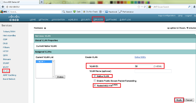
- Create an SSID and assign the VLAN.

- Broadcast the SSID.
Method 2: Configure the SSID on an AP with a CLI
- Configure the SSID and map it to a VLAN.
Enable
Conf ter
Dot11 ssid Cisco
Vlan 50
Authentication open
Guest-mode
End
- Configure the Dot11 Radio 0 and Gigabit Ethernet interfaces.
>Conf t
interface Dot11Radio 0
ssid Cisco
Exit

Interface Dot11Radio 0.50
Encapsulation dot1Q 50 native
Bridge-group 1
Exit

Interface GigabitEthernet 0
Bridge-group 1

Interface GigabitEthernet 0.50
Encapsulation dot1Q 50 native
Bridge-group 1
-------------------------------------------
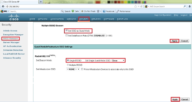
Multiple SSID
---
Multiple SSID
In this example I will show you how to configure multiple SSIDs on a dual-band autonomous Cisco access point. The interface “Dot11Radio0” is for 2.4 GHz and “Dot11Radio1” for 5 GHz. We will configure three SSIDs for different VLANs.
Create your VLANs for your wireless network:
dot11 vlan-name Intern vlan 1
dot11 vlan-name Scanner vlan 10
dot11 vlan-name Guest vlan 20
create your SSIDs (bound to the VLANs):
dot11 ssid TestIntern
vlan 1
authentication open
authentication key-management wpa version 2
mbssid guest-mode
wpa-psk ascii [Your PreSharedKey]
!
dot11 ssid TestScanner
vlan 10
authentication open
authentication key-management wpa version 2
mbssid guest-mode
wpa-psk ascii [Your PreSharedKey]
!
dot11 ssid TestGuest
vlan 20
authentication open
authentication key-management wpa version 2
mbssid guest-mode
wpa-psk ascii [Your PreSharedKey]
configuration of the 2.4 GHz interface
interface Dot11Radio0
no ip address
!
encryption mode ciphers aes-ccm
! aes-ccm is for WPA2:
encryption vlan 1 mode ciphers aes-ccm
!
encryption vlan 10 mode ciphers aes-ccm
!
encryption vlan 20 mode ciphers aes-ccm
!
ssid TestGuest
!
ssid TestIntern
!
ssid TestScanner
!
antenna gain 0
stbc
beamform ofdm
mbssid
station-role root
Sub-interfaces for VLAN-tagging:
interface Dot11Radio0.1
encapsulation dot1Q 1 native
bridge-group 1
bridge-group 1 subscriber-loop-control
bridge-group 1 spanning-disabled
bridge-group 1 block-unknown-source
no bridge-group 1 source-learning
no bridge-group 1 unicast-flooding
!
interface Dot11Radio0.10
encapsulation dot1Q 10
bridge-group 10
bridge-group 10 subscriber-loop-control
bridge-group 10 spanning-disabled
bridge-group 10 block-unknown-source
no bridge-group 10 source-learning
no bridge-group 10 unicast-flooding
!
interface Dot11Radio0.20
encapsulation dot1Q 20
bridge-group 20
bridge-group 20 subscriber-loop-control
bridge-group 20 spanning-disabled
bridge-group 20 block-unknown-source
no bridge-group 20 source-learning
no bridge-group 20 unicast-flooding
the same configuration for the 5 GHz interface:
interface Dot11Radio1
no ip address
!
encryption mode ciphers aes-ccm
!
encryption vlan 1 mode ciphers aes-ccm
!
encryption vlan 10 mode ciphers aes-ccm
!
encryption vlan 20 mode ciphers aes-ccm
!
ssid TestGuest
!
ssid TestIntern
!
ssid TestScanner
!
antenna gain 0
no dfs band block
stbc
beamform ofdm
mbssid
channel dfs
station-role root
!
interface Dot11Radio1.1
encapsulation dot1Q 1 native
bridge-group 1
bridge-group 1 subscriber-loop-control
bridge-group 1 spanning-disabled
bridge-group 1 block-unknown-source
no bridge-group 1 source-learning
no bridge-group 1 unicast-flooding
!
interface Dot11Radio1.10
encapsulation dot1Q 10
bridge-group 10
bridge-group 10 subscriber-loop-control
bridge-group 10 spanning-disabled
bridge-group 10 block-unknown-source
no bridge-group 10 source-learning
no bridge-group 10 unicast-flooding
!
interface Dot11Radio1.20
encapsulation dot1Q 20
bridge-group 20
bridge-group 20 subscriber-loop-control
bridge-group 20 spanning-disabled
bridge-group 20 block-unknown-source
no bridge-group 20 source-learning
no bridge-group 20 unicast-flooding
now we need to bridge the wireless data to our cable-network:
interface GigabitEthernet0.1
encapsulation dot1Q 1 native
bridge-group 1
bridge-group 1 spanning-disabled
no bridge-group 1 source-learning
!
interface GigabitEthernet0.10
encapsulation dot1Q 10
bridge-group 10
bridge-group 10 spanning-disabled
no bridge-group 10 source-learning
!
interface GigabitEthernet0.20
encapsulation dot1Q 20
bridge-group 20
bridge-group 20 spanning-disabled
no bridge-group 20 source-learning
the configuration ip address will be configured to the bridge interface:
interface BVI1
ip address 192.168.1.50 255.255.255.0
keep in mind that the “native” encapsulation in this example is “untagged VLAN 1” so if you configure a VLAN trunk to the access point, VLAN 1 needs to be untagged.
---
Cisco WLC High Availability
First you can completely configure the first WLC as you wish. In our example we are using the following IP addresses:
WLC Active
Management: 192.168.150.61 /22
Redundancy-MGNT: 192.168.150.63 /22
Service-Port: 192.168.1.61 /24
Virtual: 192.0.2.1
Management: 192.168.150.61 /22
Redundancy-MGNT: 192.168.150.63 /22
Service-Port: 192.168.1.61 /24
Virtual: 192.0.2.1
WLC Passive
Management: 192.168.150.62 /22
Redundancy-MGNT: 192.168.150.64 /22
Service-Port: 192.168.1.62 /24
Virtual: 192.0.2.1 (needs to be the same as the Active Unit)
Management: 192.168.150.62 /22
Redundancy-MGNT: 192.168.150.64 /22
Service-Port: 192.168.1.62 /24
Virtual: 192.0.2.1 (needs to be the same as the Active Unit)
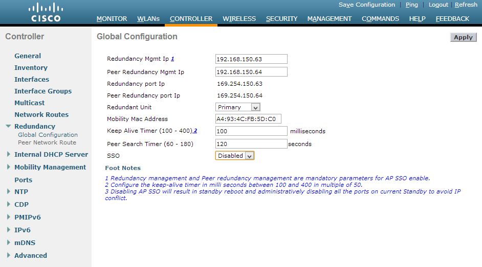
Configure only the management-, service-port- and virtual-interface like this on the first WLC:
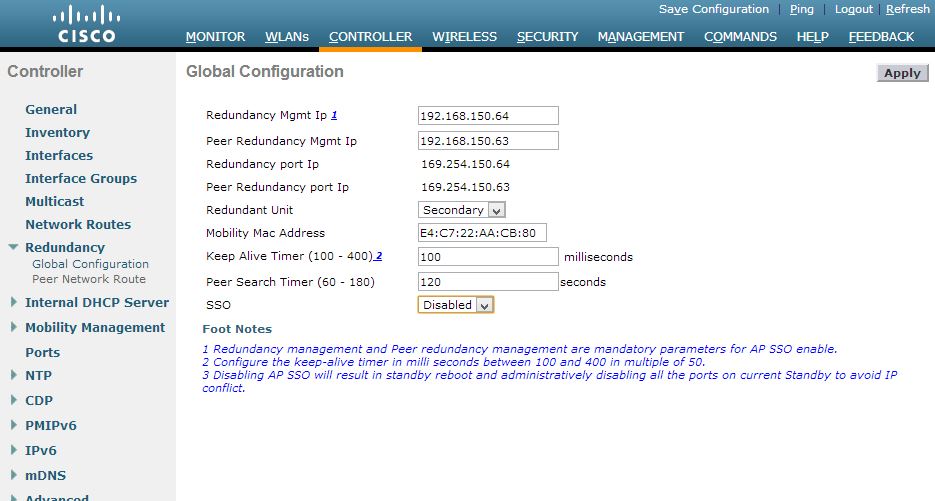
Configure the second WLC (our standby unit) with the IP addresses given above with console to access the webinterface. Keep in mind to active it with a shell-command, posted some month ago in this post. Now we will configure the redundancy-settings as shown in the images below:
First WLC:
Second WLC:
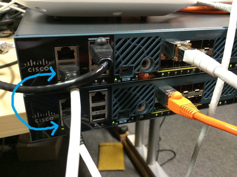
After this step, please click on the Apply-Button to save this settings. Now you can connect both WLCs at the Redundany Port (RP) with a single copper cable:
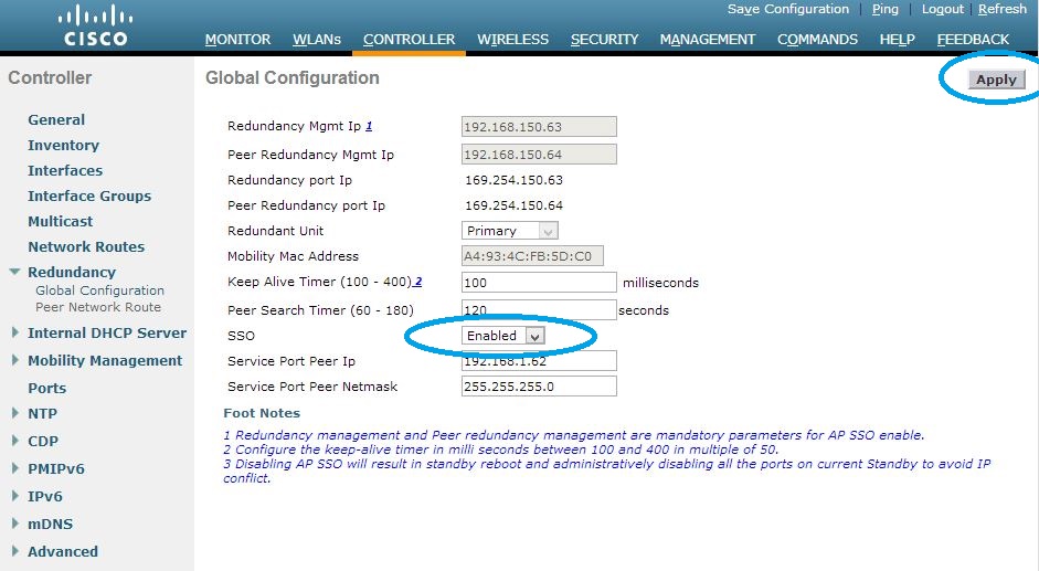
Both controllers are still unique and didn’t see each other. To build the cluster, we will activate the function “AP SSO” on both WLCs. After applying the settings, the controllers are rebooting. I recommend to connect a console cable to the standby unit to watch the redundancy process. Active the “AP SSO” function on the first WLC, click on Apply. After this, do the same on the second WLC:
The redundancy port IP addresses are configured automatically. You will see that the first and second octet will change to 169.254.x.x. From the console port of the second WLC, you can see the comparing of the configuration and licenses:
Starting Redundancy: Starting Peer Search Timer of 120 secondsFound the Peer. Starting Role Determination…Error:Unable to add Licenses on secondary Controller
Standby started downloading configurations from Active…Standby comparing its own configurations with the configurations downloaded from Active…Startup XMLs are different, reboot required
Restarting system. Reason: rsyncmgrXferTrasport ..Updating license storage … Done.
Restarting system.
after the second reboot:
Starting Redundancy: Starting Peer Search Timer of 120 secondsFound the Peer. Starting Role Determination…
Standby started downloading configurations from Active…Standby comparing its own configurations with the configurations downloaded from Active…Startup XMLs are same, no reboot required
Standby continue…
ok
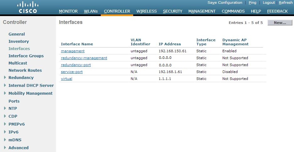
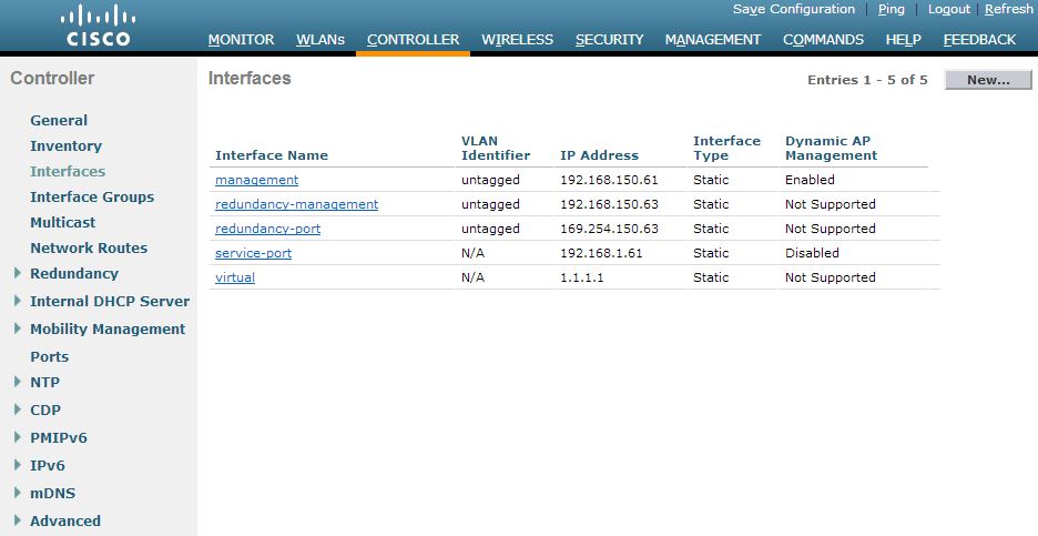
The whole cluster is now reachable via the first management interface (192.168.150.61 in our example) so the IP address 192.168.150.62 is now free but I would keep this address blocked in your network. Please check the redundancy summary and interfaces after your cluster-configuration:
Interfaces:
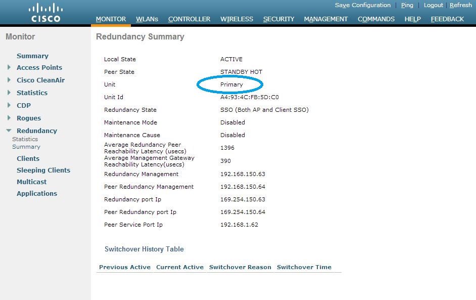
redundancy-summary at the active WLC via webinterface:
redundancy-summary on the standby WLC via shell:
(Cisco Controller-Standby) >show interface summary
Number of Interfaces…………………….. 5Interface Name Port Vlan Id IP Address Type Ap Mgr Guest
——————————– —- ——– ————— ——- —— —–
management 1 untagged 192.168.150.61 Static Yes No
redundancy-management 1 untagged 192.168.150.64 Static No No
redundancy-port – untagged 169.254.150.64 Static No No
service-port N/A N/A 192.168.1.62 Static No No
virtual N/A N/A 1.1.1.1 Static No No(Cisco Controller-Standby) >show redundancy summary
Redundancy Mode = SSO ENABLED
Local State = STANDBY HOT
Peer State = ACTIVE
Unit = Secondary – HA SKU (Inherited AP License Count = 25)
Unit ID = E4:C7:22:AA:CB:80
Redundancy State = SSO (Both AP and Client SSO)
Mobility MAC = A4:93:4C:FB:5D:C0
Average Redundancy Peer Reachability Latency = 1396 usecs
Average Management Gateway Reachability Latency = 381 usecsRedundancy Management IP Address…………….. 192.168.150.64
Peer Redundancy Management IP Address………… 192.168.150.63
Redundancy Port IP Address………………….. 169.254.150.64
Peer Redundancy Port IP Address……………… 169.254.150.63
-----------------------------------
Hiç yorum yok:
Yorum Gönder